Projects
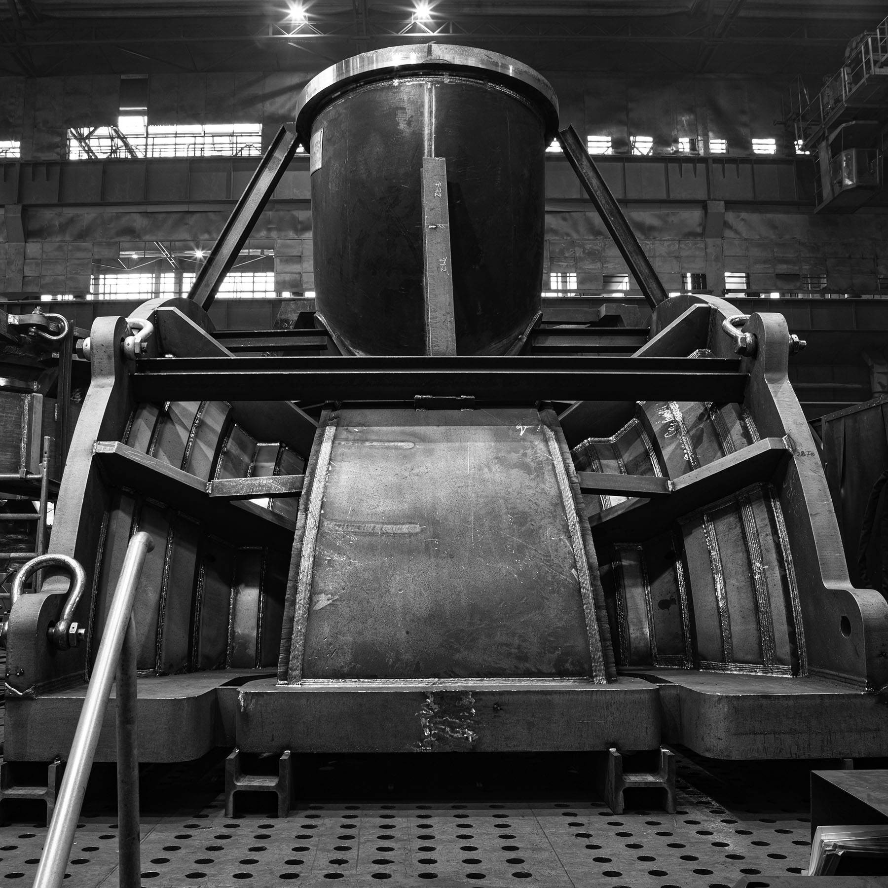
steam turbine casing
• manufactured from plates with thicknesses ranging from 40 to 240 mm • all components were cut, prepared with welding bevels, then tack-welded and fully welded • the final product was made from several sections assembled into a single unit
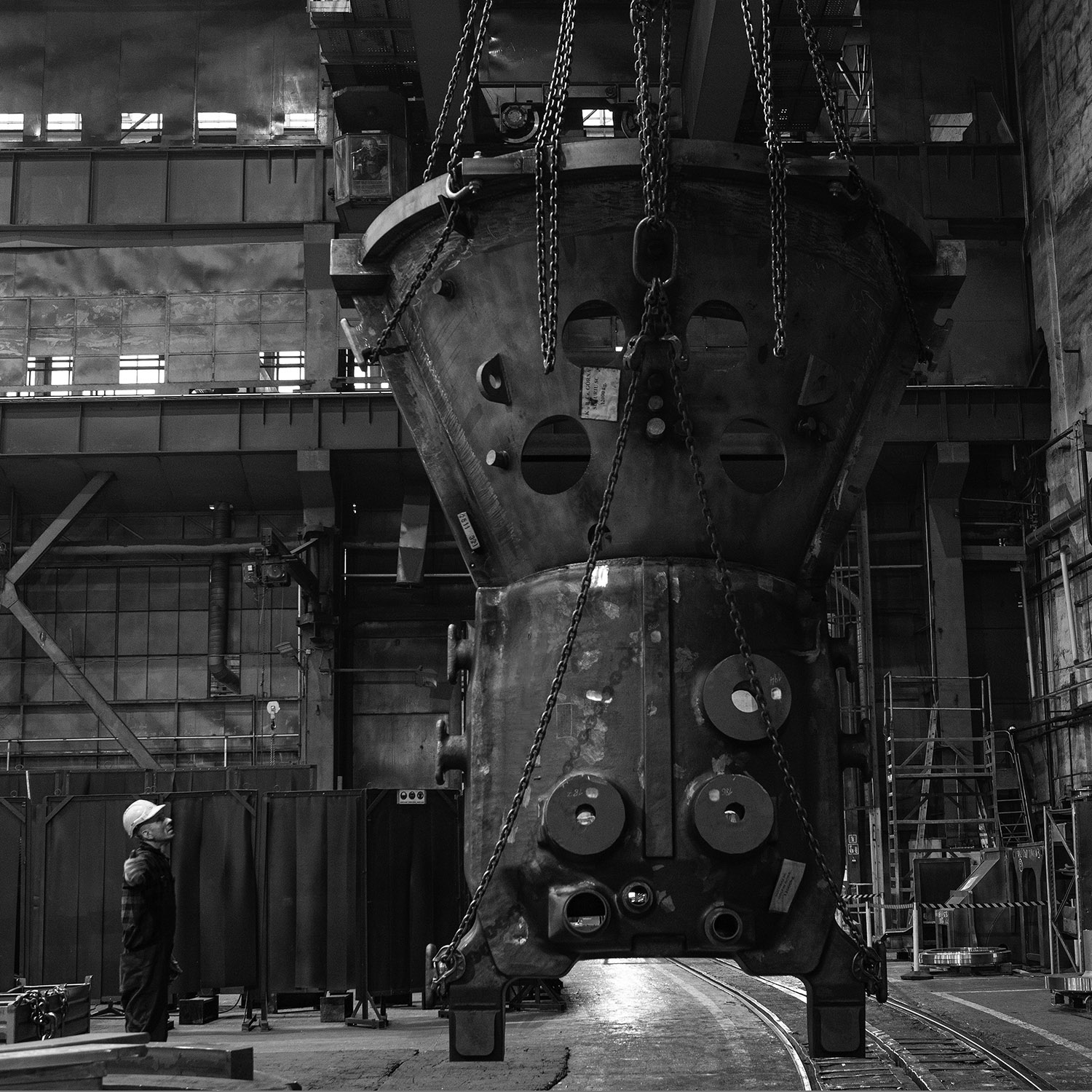
conical turbine section
• our scope of work included mechanical preparation of welding bevels using CNC machines • as well as machining of holes in the shell using a boring machine

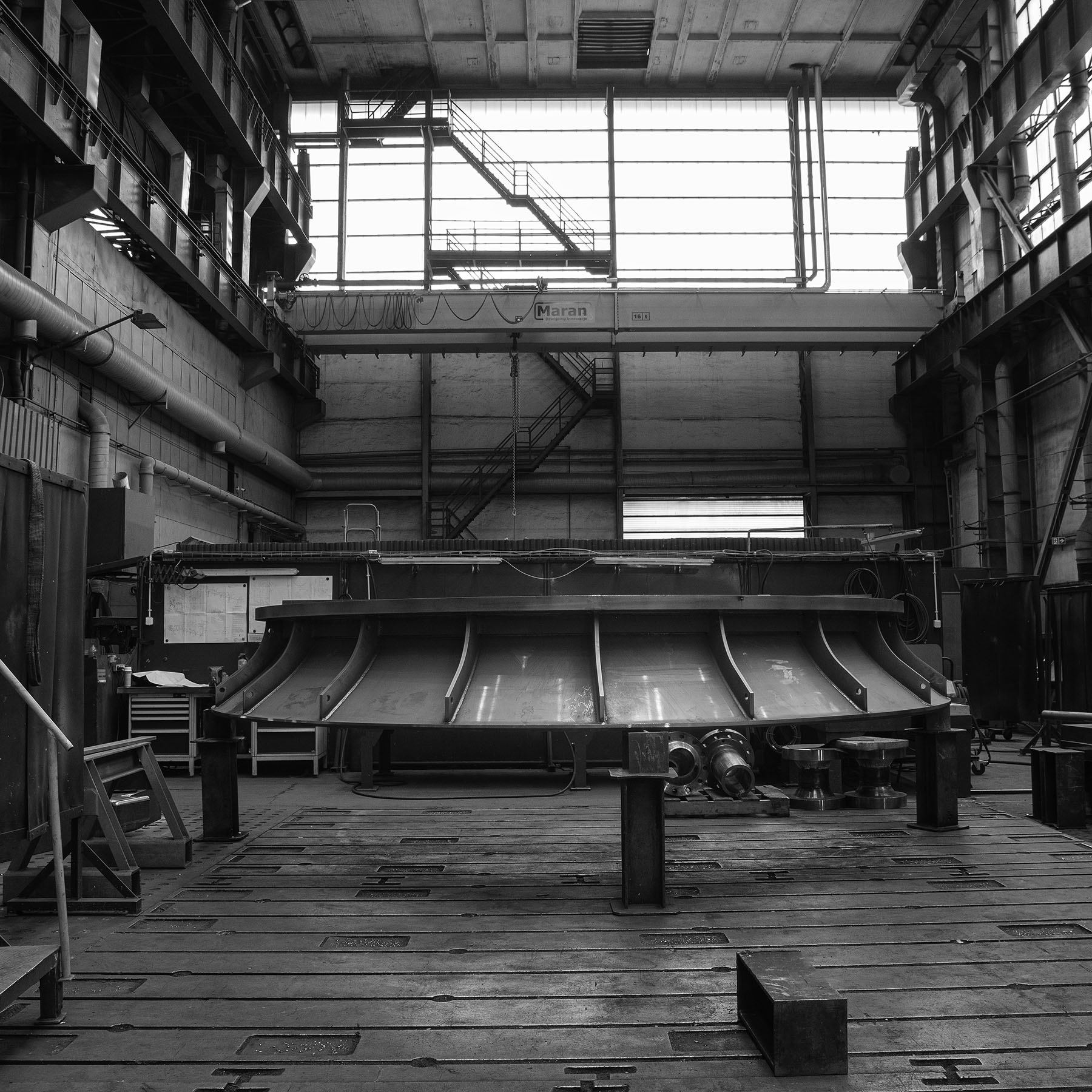
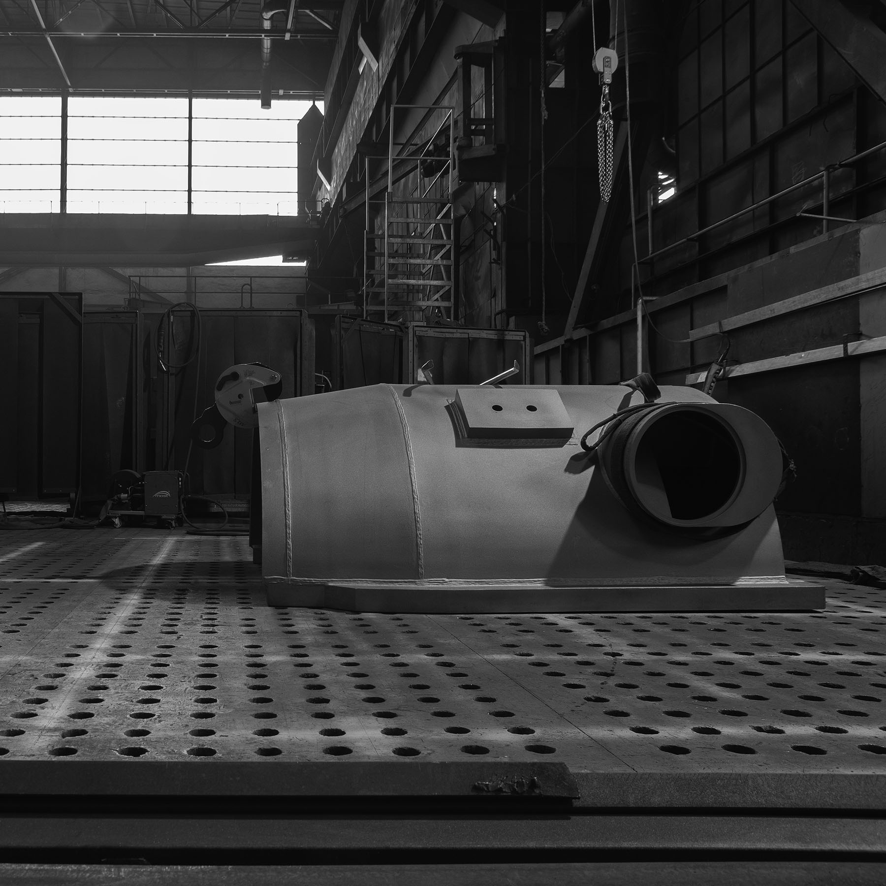
steam turbine diffuser
• the photograph shows an unrolled diffuser shell with a diameter of 5,000 mm and a thickness of 6 mm • prefabricated from plates of greater thickness • a very flexible structure, difficult to stiffen • designed for steam expansion
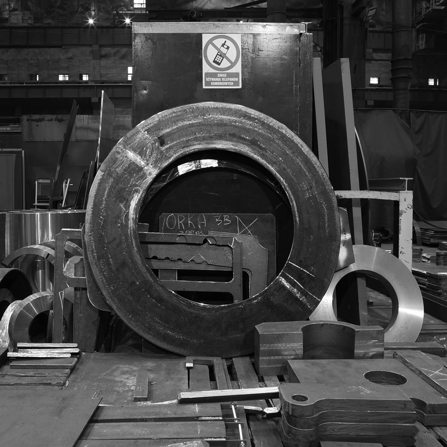
bearing casing cover
• a technologically advanced assembly combining a cast component with a non-cast housing section, including oil piping and oil channels • the component was manufactured using thermal cutting, annealing, manual and 3D beveling processes • we also carried out ultrasonic, penetrant, and visual testing
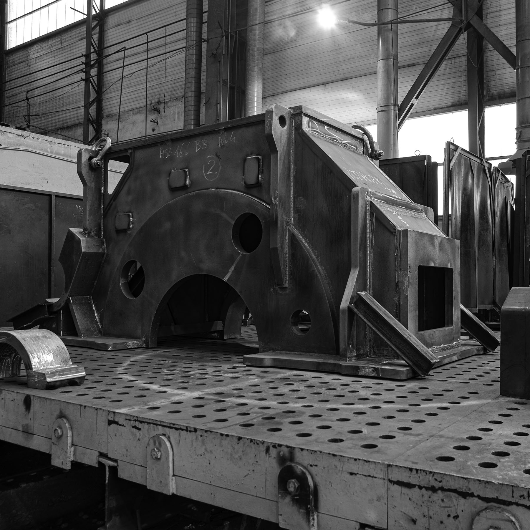
turbine casing – high-pressure stage
• from a welding perspective, this component combines two steel grades • a buffer weld overlay was applied between the cylindrical and conical sections to enable their joining • the casing also shows ground areas required for hardness measurements
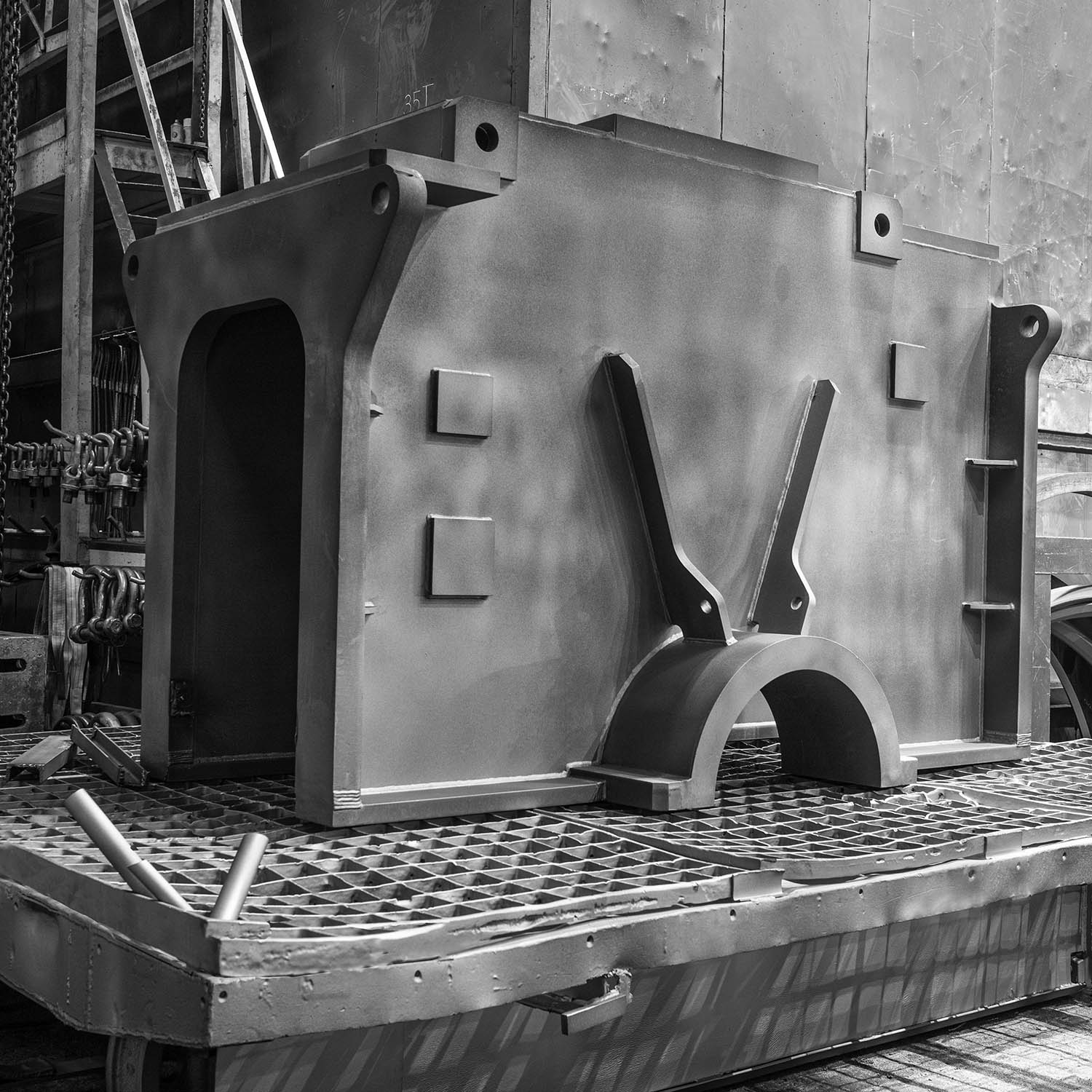
marine gearbox casing
• within the scope of this assembly, we carried out prefabrication of all components, including clamp preparation, assembly, welding, stress-relief annealing, and shot blasting
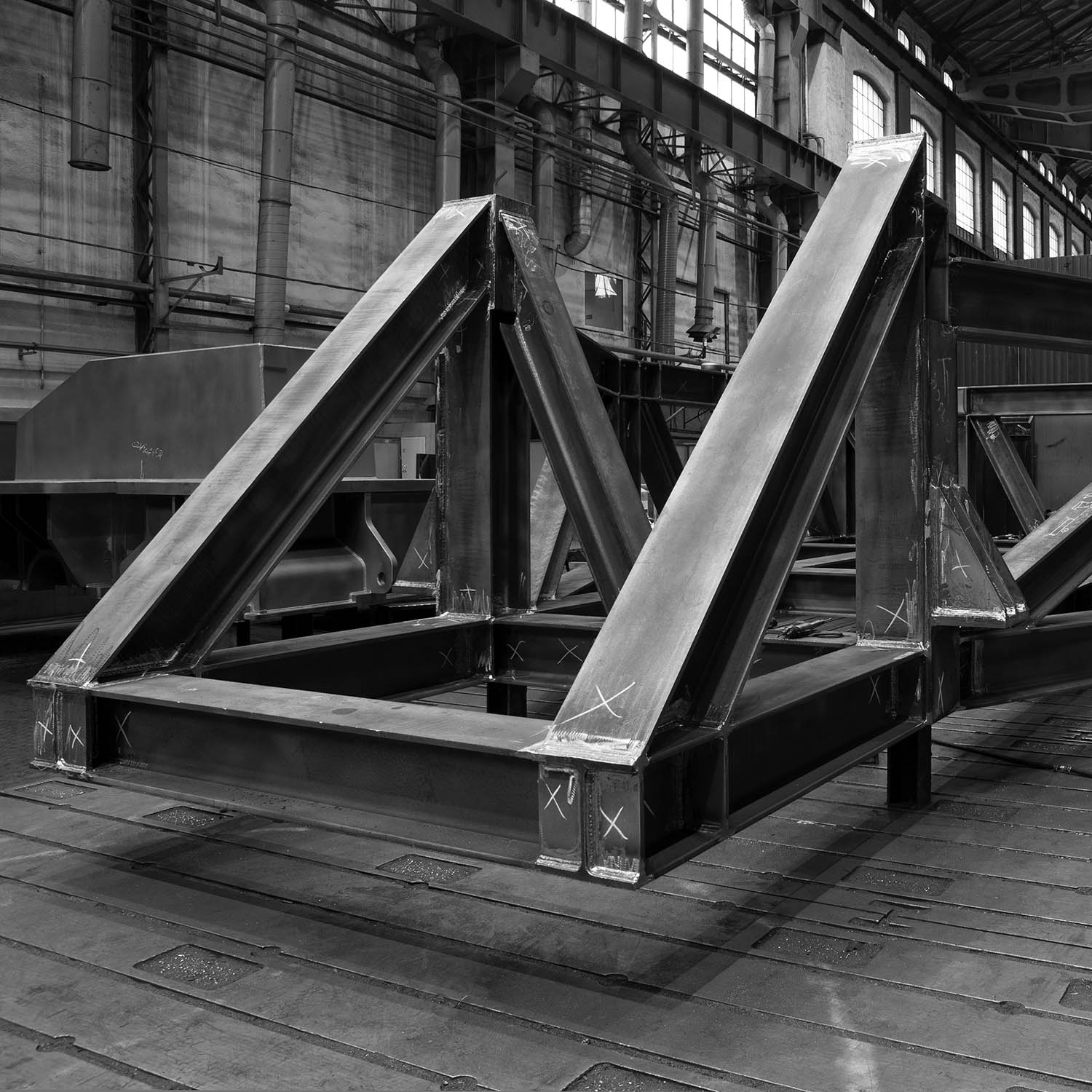
large-scale transport frame
• 11 m in length, designed for a load capacity of 150 tons • intended to securely support a turbine casing and ensure its safety during transport to the installation site • a single-use structure • scrapped after completing its task • we also manufacture frames for rotor transport at our facility
upper section of a marine gearbox
• the component was fully manufactured by our team • a major challenge were the complex clamp geometries • at a later production stage, the part will have the temporary technological braces removed, which were required for correct fabrication • and will then be transported to the shot blasting facility